06/08/2020
Demonstration Video
Here is the final demonstration video showing the organ being played by the max patch.05/08/2020
Finished Max Patch
After working on the max patch, I’ve significantly improved its functionality, see schematic diagram below: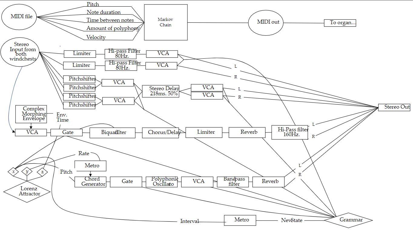
The patch is initialised by training the markov chain objects on a MIDI file. The attributes of this MIDI file; pitch, amount of polyphony, time between notes and polyphonic note duration are parsed and sent to respective markov objects. The patch uses a combination of real-time MIDI generation as well as various generative processes which control different audio processing, synthesis, melodic and structural parameters.
The overall structure is determined by a grammar, housed in the structure-grammar sub-patch. The grammar starts with an initial list of letters, representing various ‘states’ the patch can be in, - A B C B D E. This list is then iterated and appended with another letter, depending on the letter which came before it.
This generates a long list of ever-changing states with little repeating patterns, allowing me to iterate through the list and tell the rest of the patch what state it’s in. The length of each section is determined by the output of a Lorenz attractor, housed in the tb.lorenz subpatch. The defining equations for the attractor are implemented in the gen object, with new values being calculated every 100 milliseconds. This leaves me with three modulation sources from the x, y and z outputs of the attractor which are mapped to different parameters around the patch. After training the markov models on a MIDI input, the patch can begin by pressing a single toggle, which sets all the processes in motion. Using two LOM UsiPro omnidirectional condenser microphones (one for each windchest), the live input from the organ is passed through a limiter and an 80hz low cut filter before being sent through other DSP processes.
The dry organ signal is then sent to a pitch shifter, implemented with pitchshift~ objects, located in the organ-pitch-shifting sub-patch. If the patch is in a state where pitch shifting automation is active, the output of a brownian object selects which pitch shift ratio is selected from a coll object, where a list of possible pitch shifting ratios are stored. There is independent pitch-shifting for each channel of the stereo input signal. The transposed signal is then sent though a delay, before being sent to the master output channel.
The sin-chords sub-patch generates a slow chord progression, with the x and y output of the Lorenz attractor mapped to pitch and timing parameters, with the z output controlling the duration of each note. The x output is interpreted as a MIDI number by capturing the output of the Lorenz attractor at a given point using sample-and-hold, this MIDI number corresponds to a frequency stored in a coll object which acts as a simple pitch-quantiser.
The dry signal of the organ is sent through a VCA modulated by a complex envelope generator housed in the gated-organ subpatch. The shape and length the envelope depend on the outputs of the Lorenz attractor. This modulated signal then enters a resonant delay line, found in the stereo-delay subpatch before being sent to the output channel.
10/07/2020
Fitting all the pieces together
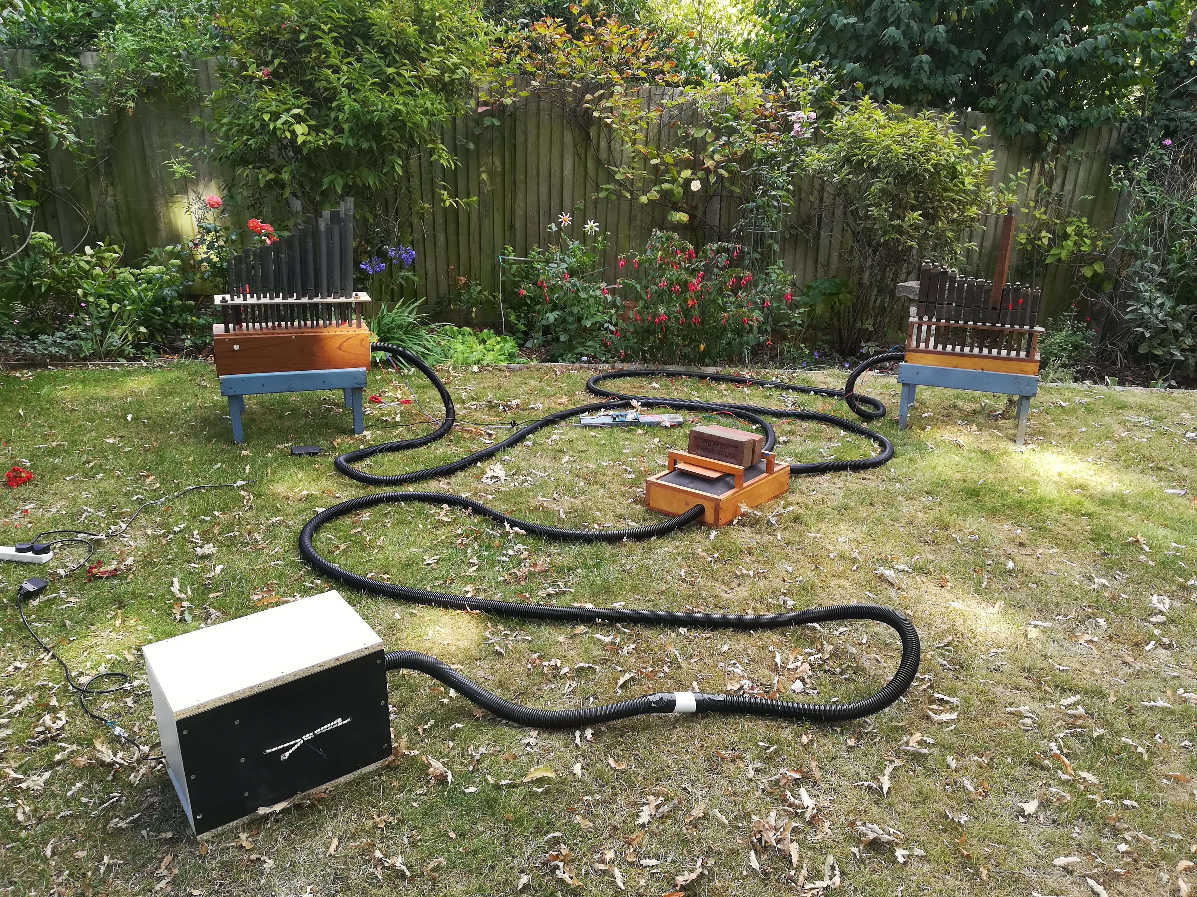
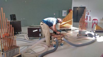
Set up the organ in the garden with the ducting and blower box for the first time, all sounds great although some of the motor noise travels down the ducting to the bellows which amplifies it a bit. This isn’t a big problem though.
05/07/2020
Extending the max patch, adjusting holes for ducting
I built upon the initial Markov chain patch by adding audio processes, including a stereo pitchshifter, delay and complex envelope generator, pictured below. I plan to control these processes with a grammar later on.A few days after this the ducting that I ordered had arrived, 15 metres of 30mm diameter vacuum tubing. This meant I can adjust the inlet holes on each of the modules so the ducting can simply screw in. I did this by either expanding the existing hole using a rasp drill bit, or by mounting a plywood plate over the existing hole.
01/07/2020
Building Blower Box & Making an extension cable for both windchests
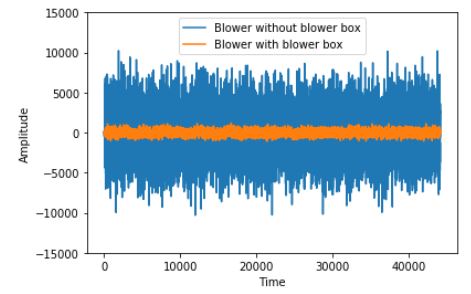
After settling on a cheap eBay inflatable mattress blower, I had to create a box to house it and to reduce the motor noise which was extremely loud.After cutting a up some sheets of MDF 23mm thick to the required sizes, with help from my Dad, we assembled a simple 5-sided box, leaving one side off so we could work on the inside. The interior walls were then coated with 30mm thick rock wool by gluing it on to the sides. The blower is suspended in the centre of the box using 4 bungee cords, which are attached to each top corner. Two baffle panels were cut to size and mounted on the inlet side of the box, then both coated in rock wool. A 30mm hole was drilled in the opposite side of the box to thread the ducting, which is connected to the outlet hole of the blower, through the wall to allow for it to be coupled to another piece of ducting, and then on to the bellows. I fitted the blower power cable with a speed controller pot and switch, so the blower could be switched on and off externally. The box worked well, greatly reducing the sound of the blower to a gentle hum. I tested the reduction in noise by recording the blower from 1 metre away when in and out of the blower box. As one can see from waveforms below, there is a substantial difference:
A couple of days later I made some extension cables for both the windchests so they could be placed further apart, soldering on a longer wire to the positive wire which protrude out of one end of the case so they can be spaced further apart – each cable is about 4 ft long.
15/05/2020
Fifth meeting with supervisor, deadline extension and initial software ideas
As a result of my application for extenuating circumstances were approved – we discussed the best ways to move forward with the project as a result of the extension, it was agreed that in lieu of being able to order the parts needed to finish the organ, I should focus on the software. I have experimented this week using a series of Markov chains to generate MIDI data using MaxMSP, with the ml.star library. A screenshot of the patch can be seen here: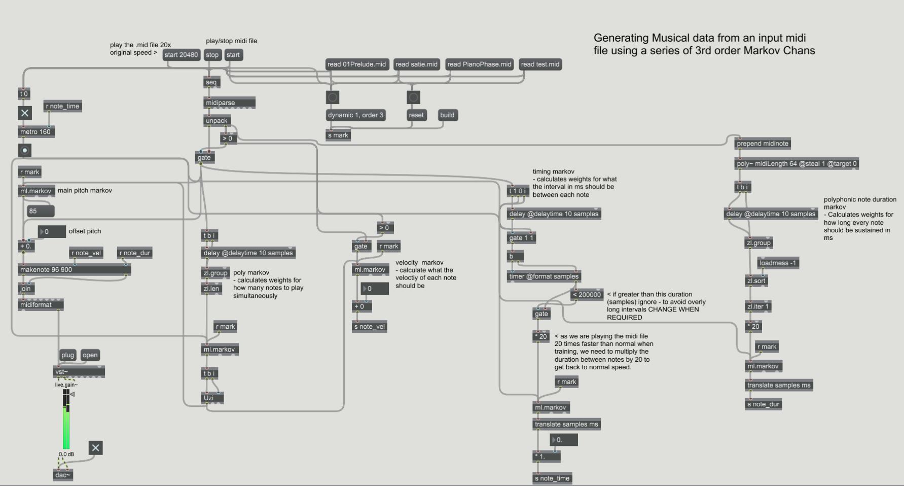
The patch takes a .mid file and parses different features (pitch, amount of polyphony, velocity, time, poly note duration) to 5 different 3rd order markov objects, which are then trained on the data. Markov chains seem to be very musical and a great way to generate original material which relates to a given melody of musical phrase. These markov processes could be made more interesting when an additional layer of processing is appended to allow for more an even more musical feel. This could involve capturing the output of the markov chains in to a buffer, and allowing for repeated phrases to emerge, as the output of the markov on its own sounds a bit to noodle-y to listen to withhold my attention as a listener.
07/05/2020
meeting with supervisor IV
During this meeting we discussed my difficulties in completing the physical aspect of the project (building the organ) as a result of the Covid-19 lockdown restrictions worldwide, and suggested I look into the possibility of a deadline extension17/04/2020
meeting with supervisor III – reviewing draft report
During this meeting we I received feedback on my project report draft. As Matt suggested, I wrote up one chapter in full, and planned the rest of the report using bullet points and discussing what each section of the report would include. Several helpful suggestions were made summarised here:- Differentiate between ‘Aims’ and ‘Objectives’
- o Objectives = what am I doing to achieve aims
o Aims = Higher-level goals e.g. make a portable instrument, extend possibilities of pipe organ - Be sure to address each stated objective in evaluation section
- o Headings can be objectives e.g. midi board, moduar design etc.
o How portable is it? What do I mean by portable? - Intuivity
- o Explain what my concept of intuitive in is - unpack my definition
o Neilson’s usability metrics
o does the system express its state - good visual feedback?
o easy to manipulate data? - Define musically useful
- o Limitations within software so produces expected output
o What is it about the software that makes it musically useful? - Design
- o Screenshots of software in different states
o Audio examples - Musical Discussion
- o Discussion on experimentation
o Think about whether ‘performativity’ section is still needed - Ideas to explore for software:
- o 12 tone row manipulation, serial techniques
30/03/2020
restoring principal pipes and making a custom rackboard
I managed to order 19 pipes plus some spares for windchest 2, ranging from G3 to F5. These pipes belong to the Principal rank which have a stronger clearer tone than stopped diapasons I have already.Sadly, a lot of them were damaged in transit and misshapen, most of them did not sing at all. The pipes seemed relatively malleable, so I simply banged them back into shape with a hammer and made small adjustments to the angle of the upper lip and languid and managed to fix almost all of them. As I was sent some extra pipes, I still have enough to fill the windchest.
After this I set about making a rackboard prototype out of cardboard so I can fit the pipes to the chest. To do this I simply marked out the holes of the original rackboard on to a sheet of cardboard and cut them out, then enlarging them to the appropriate size for the diameter of each pipes, now they all sit nicely on the chest. I confirmed this by hooking the magnets up to the midi2Org board and using the inflatable mattress blower to and they all sing well.
15/02/2020
fitting pipes to windchest 1, acquiring more pipes for second windchest
To test the pipes and get an idea of how powerful the blower must be, I fitted 13 of the Gedackt (wooden stopped diapason) pipes I had bought to the windchest. I used an inflatable mattress blower running straight into the inlet hole of the windchest (no bellows). The pipes all sounded relatively good, a video of this intial test can be seen here.The second windchest was designed for small, high register pipes, as the holes on the rackboard the pipes are supposed to fit through are very small. I wanted to get another rank of pipes in a slightly lower register, so I would have to make a custom rackboard and perhaps increase the size of the toe holes if necessary. I’m currently talking to an Organ builder to see if he can supply me with something suitable.
05/02/2020
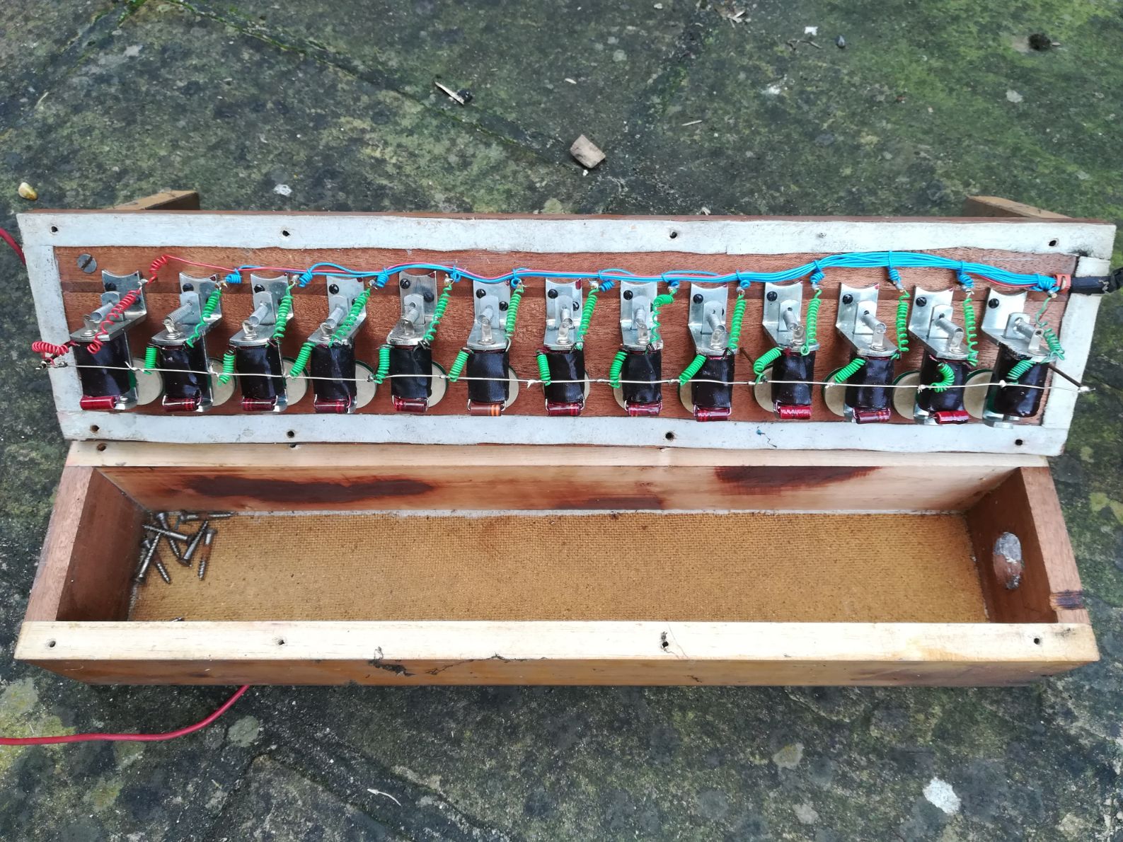
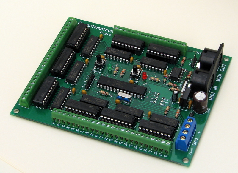
testing Magnets with Midi2Org board and Wiring
After fleshing out a general plan for modular design of the organ, I set about testing the windchests I had bought to see how they function, as well as make any necessary repairs or alterations. Surprisingly, upon opening up the first windchest all the original wiring was still very much intact, and the magnets all looked clean, although the felt pads which plug the toe hole were quite worn out and dusty, but they still provided a good seal. (picture) There are thirteen magnets in this chest, which require two connections. The ground wire of every magnet is attached to a copper rod which acts as the common ground, this rod is connected to a terminal to the outside of the chest making it easy to hook up to the common ground of other windchests, as well as to the midi2Org board. The positive wires are wound together and protrude out one side of the windchest, only about 4 inches, so an extension cable must be made in order to reach the terminals on the midi2org board. I now needed to hook up the magnets to the midi2Org board to check If both the board and the magnets are working correctly.Testing the magnets with the board was very simple, the terminals one the board are marked 1-64, each of these terminals can be assigned a MIDI note to trigger them, after configuring the MIDI number and channel assignments I could easily trigger every magnet on the board using a virtual MIDI keyboard and MIDI interface. The midi2ord board requires two power supplies, one for the magnets and the other for the logic part of the boards, detailed below. Initially I used two 9 volt batteries in series to power both parts of the board.
As a result of this test, I could see every magnet on the did become magnetised, but only some with enough force to open the valve and some of them appeared ‘sticky’ - instead of a short, sharp motion when opening and closing. This could be due to a couple of reasons:
- The magnets aren’t receiving enough power to push against the spring which holds them closed by default - There’s some dirt/residue in the mechanism that need to be cleaned and lubricatedAs a result of this, I used contact cleaner and Isopropyl Alcohol to clean all the magnets, especially around the hinge on the armature which opens and closes. This seemed to greatly improve their movement; however, the power being supplied to the magnets was still not great enough to open the valves properly. I then experimented with different power supplies suggested in the Midi2Org board manual and found that a 19Volt 3Amp supply was the perfect amount to power both the board and the magnets on this chest, giving me 13+ note polyphony. After these adjustments all the valves opened and closed perfectly.
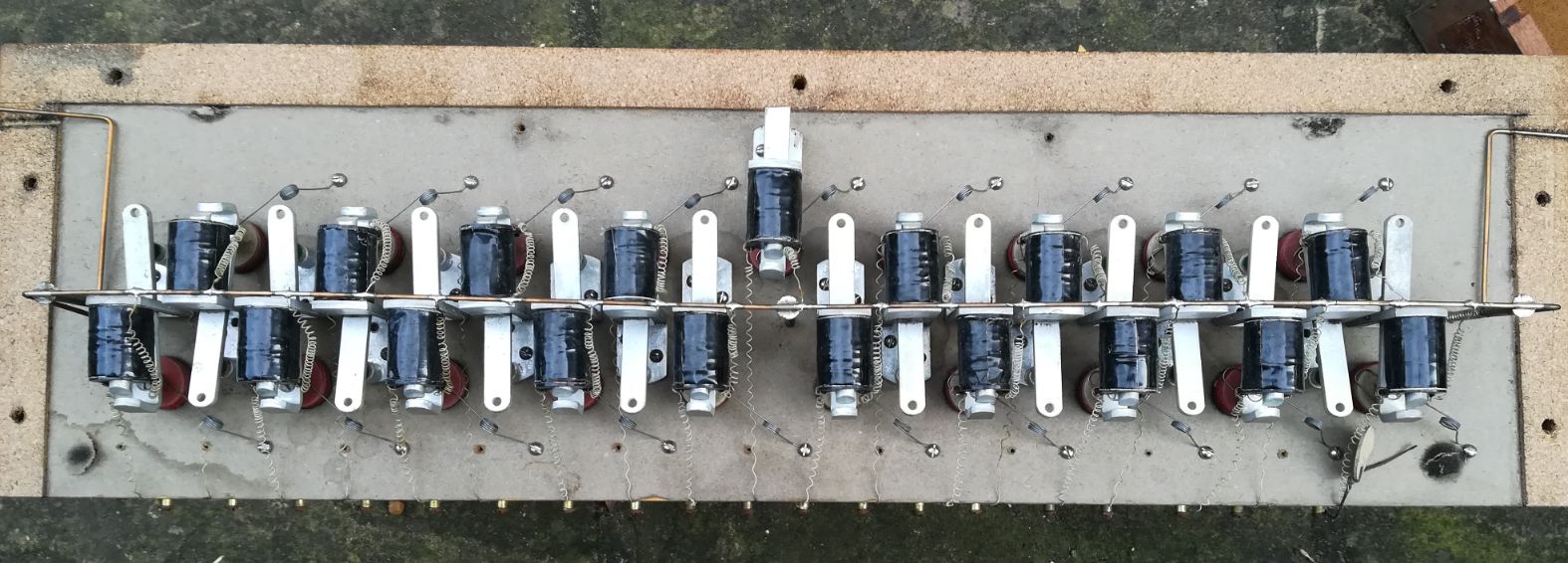
The second, larger 19-note windchest was slightly older, opening it up to look at the wiring, it had significantly degraded, although the common ground rail was still intact and looked fairly rigid. This chest seemed to use a different system to organise the internal wiring. Each + wire was attached to a small terminal on the outside of the chest, I decided that the wire organisation on windchest 1 was a lot cleaner as well as easier to debug and transport. As a result of this I stripped the + wires from the terminals and re-soldered them on to small nails next to each magnet, I then soldered a further longer wire, one for each nail which I then bunched together using heatshrink tubing so they could protrude out of one end of the case. This allows me to easily hook them up to the midi2Org board and test the magnets.
Luckily these magnets seem to work fine with the same PSU as windchest 1, although two magnets are completely broken so had to be removed. Replacements can be sought at a later date.
24/01/2020
meeting with supervisor II
During the meeting I told Matt of my progress in acquiring the majority of the hardware and discussed how to further advance the project. I’ll spend the next week trying to fix up and test the windchests, checking each of the magnets are working by connecting them to the midi2org board. After that, I’ll use an air compressor to see if its possible to get some sound out of the pipes. We then discussed ideas for the software control system, with Matt suggesting I look in to various ML libraries tailored for use in a musical context.19/01/2020
visiting an organ builder + soldered midi2Org board
On the 19th January I travelled to Stratford-upon-avon to meet Dave Edwards, an ex-organ builder who has amassed a vast collection of obsolete organ parts over his 60 years in the industry, spread between 3 large storage facilities . He provided great advice and assistance, and kindly sold me a 19 note windchest, 13 note windchest and 36 wooden stopped diapason pipes for a discounted price. This means the only piece of hardware left to buy is the blower – research into the exact type of blower that could be used will happen in the coming weeks.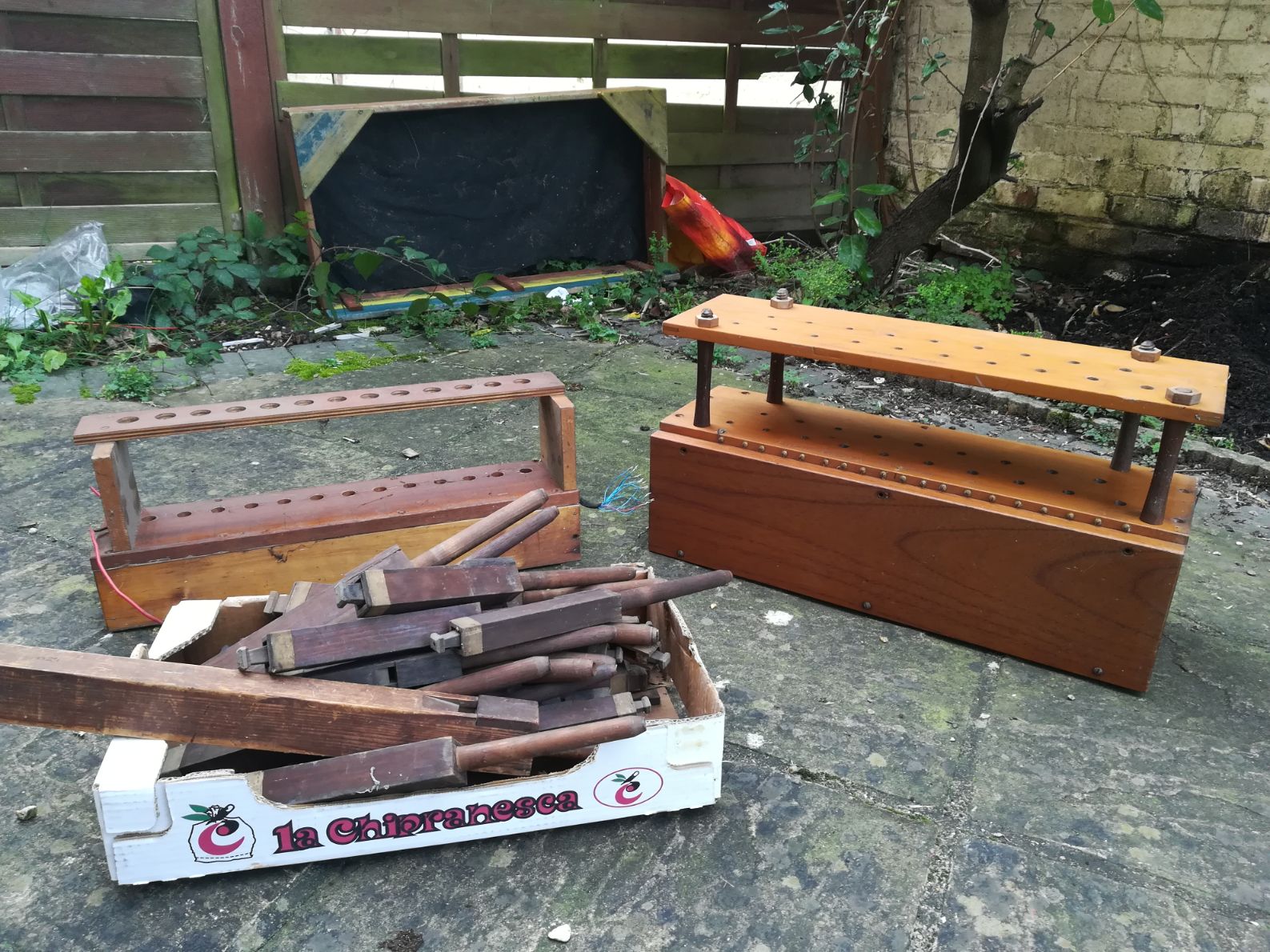
17/12/2019
magnets in the 19-note chest
The windchests are all fitted with magnets already, which makes things a lot easier, although I’ll probably have to do some restoration as they are about 30-50 years old, but this shouldn’t be more complicated than replacing some of the wiring. I’ve also soldered the midi2Org 64 board DIY kit I ordered and it’s working as expected. The board uses a 9 volt battery to power the logic parts, and I’ll use a 12 volt 1 amp transformer for the solenoids, which should give me about 6-10 note polyphony.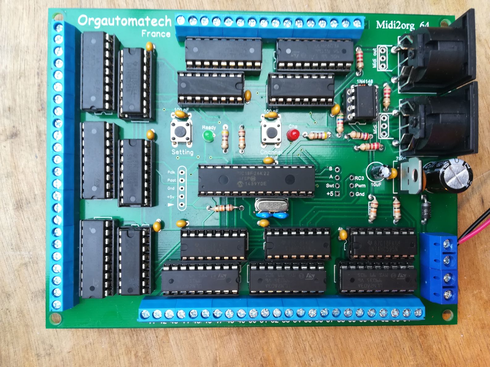
17/12/2019
first prototype and possible air flow design
As suggested by my supervisor, I set about creating a simple prototype – air flowing in to a pipe which is controlled by a computer. This prototype uses an air compressor fed in to a pneumatic solenoid valve, controlled by an Arduino and TIP120 transistor via Max MSP to open and close the valve [video].Overall the prototype works but does have some drawbacks. The solenoid has a very small valve – this greatly reduces the air flow, meaning that the input air would have to have a much higher static pressure than an electric blower can provide, so I would have to use an air compressor to power the organ. Using this design for the organ would make it a lot easier to build though, it would simply consist of connecting each organ pipe to the compressor via copper piping, with a solenoid before the pipe hole. This could perhaps be a method to use for the organ should other ways to route the air to the pipes prove unsuccessful.
14/12/2019
meeting with supervisor I
I had my first meeting with my supervisor, in which I talked through my idea for the project. We discussed the possible difficulties I would face in constructing the organ and decided to break down the construction process in to a series of discrete milestones, the first being to create a basic first prototype with a computer controlling the flow of air in to one pipe. We also discussed possible computational processes to bring the project more into the world of computing, and he suggested I look in to some kind of self-regulating system where the computer would then listen to the output and potentially modify the control input in response. He later emailed me, Ross Ashby’s Homeostat machine, as an example to look in to.26/11/2019
more research, some parts acquired & basic design
The past few days I have focused on finding out how traditional organs are constructed and their different components allowing me to settle on a basic design. The organ would consist of several discrete units (made of plywood or a similarly inexpensive material) connected via air ducting pipes, which each serve as a housing for different components of the organ. These will consist of:- An acoustically treated box for the blower
- - The blower provides the wind at the correct pressure for the pipes. This will be placed in a box lined with acoustically treated foam to minimise noise. The box will have an inlet hole, to supply the air to the blower, and an outlet hole, to pass the wind to the other components. The blower would ideally have a variable speed controller, which allows for the possibility of voltage control of the wind pressure.
- A Bellows to regulate the wind pressure, with a spill valve
- - There are many ways of constructing a wind regulator, and the exact type and regulation method will be decided after further research. If this proves too complicated to construct, a used organ bellows can easily be obtained cheaply, and re-purposed for this project.
- Windchests/wind routing system for each pipe
- - In conventional organs, the wind is directed, from the bellows, to windchests one for each rank of pipes. In organs with electro-pneumatic actions, each pipe has a dedicated electromagnet housed in the main air reservoir within the chest. When actuated, the magnet opens a small valve when the corresponding key is depressed, thus sending the pressurised air within the chest out through the pipe causing it to sound.
 The size and design of the windchests would depend on how I route the wind to each pipe, as there are various techniques for accomplishing this.
 - - To interface with the instrument, I will use an Orgautomatech midi2Org64 decoder board, allowing for control over up to 64 solenoids via the MIDI protocol. The main interface will be designed in Max MSP, but as there are so many ways to control the instrument using a computer, other avenues should also be explored
- Playing Method/User-Interface
20/11/2019
finalising idea & initial research
Since the last blog entry, I have been researching for relevant references and projects involving augmented instruments and have found some really useful sources. As a result of this research, I’ve decided to build a small organ, given that there have been many instances of hobbyists, artists or researchers constructing electro-pneumatic organs and there are plenty of research materials already published. Organ components like pipes, bellows and solenoids are also easy to obtain online relatively cheaply. Having been awarded £333.0 by the Joe Brown Memorial Award scheme, this will really help in financing the project, something that initially concerned me.
Yoshi Wada is one such composer who I have been researching. He has constructed an array of unconventional instruments including bagpipes, an adapted organ and various horns made with readily-available materials. These were used in many of his published works from c.1970-1990 (e.g. Off The Wall) and are amply documented.
A more contemporary and very relevant example of a similar project would be the Organous, designed and built by the French experimental ensemble Pancrace. This more modern take on an adapted organ uses MIDI as its interface protocol.
Both these examples seem to use a modular approach in the organs – each component housed in dedicated units and connected with tubes. This is most likely the format I will use to design the organ.Photo: tarek atoui's the reverse sessions, kurimanzutto, mexico city, 2014
15/11/2019
the beginning
For my major project, I’d like to focus my research on augmented instruments, specifically those which allow for computer control over an acoustic sound source, realising sonic possibilities not attainable by a human performer. My idea for this project came after seeing several concerts or discovering recorded music involving hand-crafted, unusual or augmented instruments, such as Xenia Pestova’s piece Magnetic String Resonance, Tarek Atoui’s The Reverse Collection or Sholto Dobie’s ad-hoc organs and droning reed instruments found on his The Ringer EP, to name just a few examples.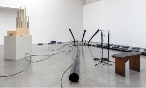 I am also interested in showcasing the final product in the form of a concert and/or recorded media, to illustrate the uses and playing techniques of the finished product in a musical/performative context.
I am currently researching instances of such instruments being made, as well as constructing some simple noise-making objects, such as those found in Bart Hopkin’s Musical Instrument Design, to decide what kind of instrument I would like the final product to be and have discovered some great references and examples in the process.
Photo: tarek atoui's the reverse sessions, kurimanzutto, mexico city, 2014